I got very bored and decided to create a brushless DC motor driver pcb. It was pretty fun going through all of the design considerations, so here we go.
Architecture

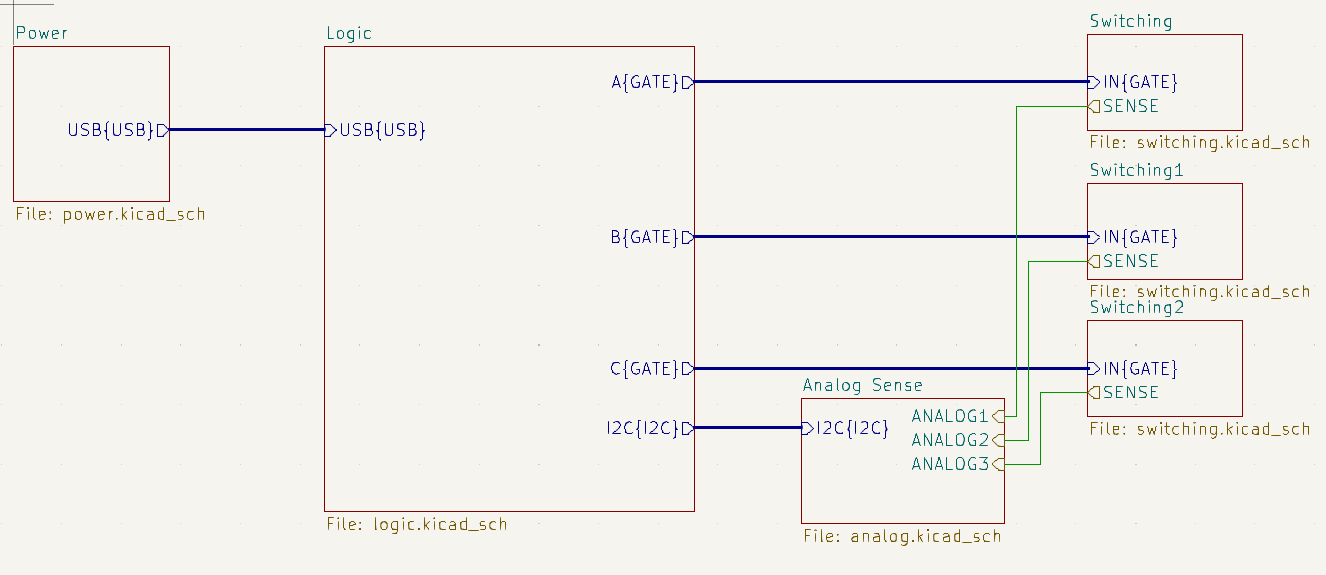
The BLDC driver is intended to be run by a MicroMod controller. This is mostly because the club I’m at uses MicroMods extensively, and I wanted to put this in that same ecosystem. Despite what the schematic implies, power does actually come from the power section, it’s just that power symbols in KiCad are global and don’t show up on hierarchal schematics. The board has usb connectivity for programming, SWD debugging, and a CAN router for future use in CAN networks. The choice of adding a CAN router is, again, mostly for future club use if we ever adopt this as our motor driver.
Motor Driver

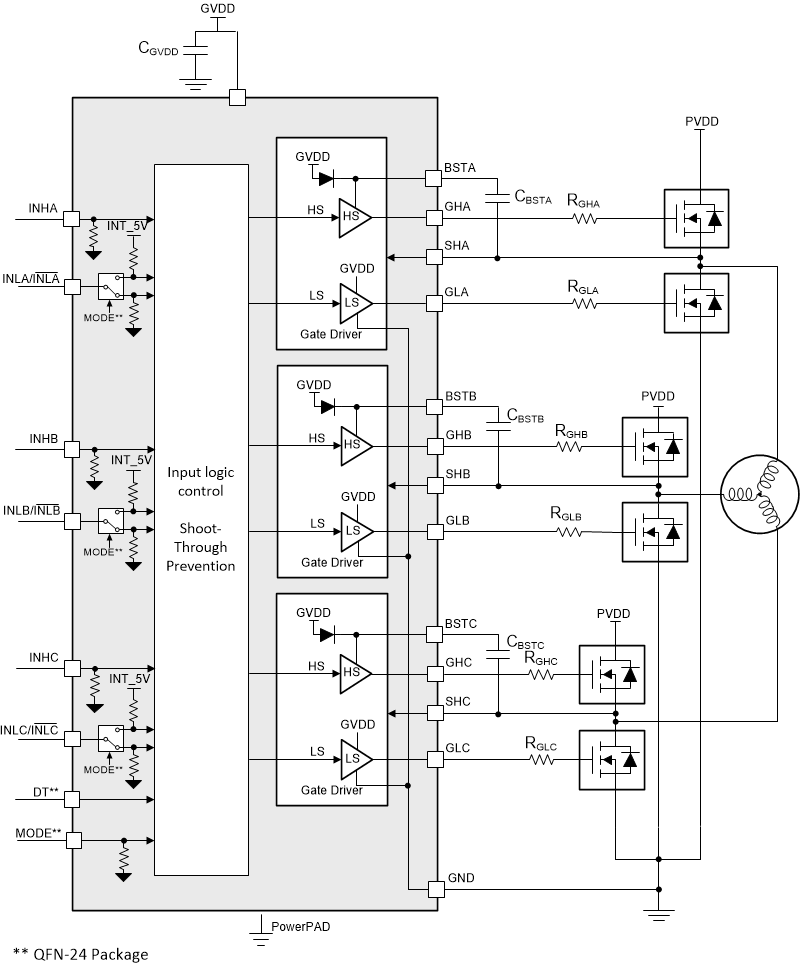
I chose the DRV8300, a three phase gate driver for this because this board was intended to drive very large motors. This means that there are three half-bridges, with NFETs on both high and low side. This necessitates bootstrap capacitors for the charge pumps for the high side mosfets, as well as a diode. The particular variant I’m using has the bootstrap diode built in, mostly to reduce complexity. Of course, a motor driver chip was chosen because most MCUs don’t have the current to PWM mosfets at higher frequencies, and also because this allows me to use NMOS on high side, which is more efficient and therefore better for driving very large motors.
Power Topology

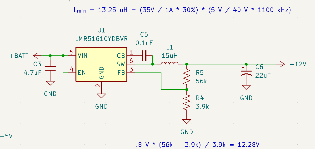
All power for the board comes from a battery connector that connects to 40 V DC. 40 V is obviously too high to use in microcontrollers or in the gate driver, which has a maximum voltage of 20 V. At first, I wanted to use a buck to step down from 40 V to 5 V so that LDO losses from powering the microcontroller is reduced. However, the gate bootstrap mechanism requires at least 5.5 V. Because of that, I increased the voltage up to 12 V, similar to the typical application in the datasheet.
The other electronics run off of a 3.3 V rail powered by an LDO. Since there’s only a microcontroller, a gate driver, and a few sensors, I believe an LDO would suffice for powering them. The LDO is powered off of the 12 V rail, since most LDO’s don’t deal well with 40 V. There’s also a separate 5 V rail for the current sensors, which is higher than the 3.3 V rail because the current sensors aren’t quite rail to rail.
Power Sensor

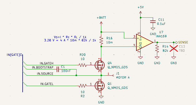
The power sensor is an INA169, which is a high side current shunt sensor. It outputs the signal in the form of a dependent current source, meaning that its gain is configurable using a resistor. They are powered off of a 5 V LDO, although in theory they could be powered off of 40 V.